
Model the route and splices
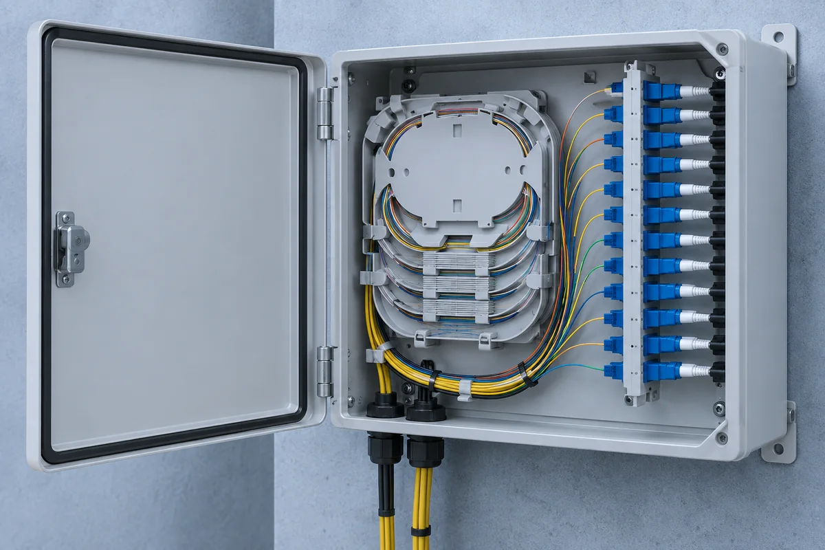
Count cables, fibers, splices and passive devices. Identify closure type, tray stack and sealing class.
A repeatable workflow reduces incompatible closures, hidden splice loss and incomplete commissioning records.
Record the endpoints, route distance, cable count, fiber count, splice capacity, availability target, mounting environment and expected service life before choosing a closure or joint box.
The checklist can be applied to aerial, duct, buried, FTTH, enterprise and industrial links.
Count cables, fibers, splices and passive devices. Identify closure type, tray stack and sealing class.
Add specified splice loss and cleaning allowance, then compare with the transmitter/receiver operating window.
Protect fiber, lay out trays in joint order, torque the lid and inspect cable entry seals.
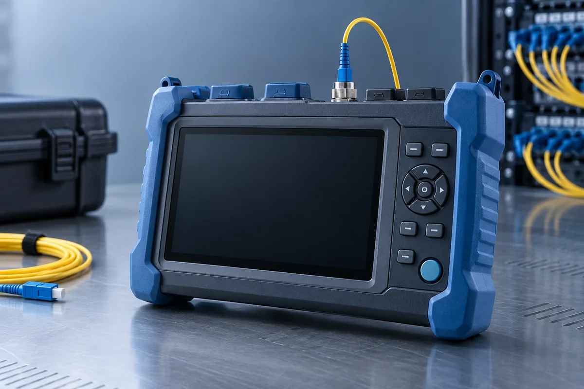
Use power/loss testing for channel acceptance and OTDR where event location or route evidence is required.
No single reading describes every aspect of a fiber optic splice closure position.
Checks contamination and fiber end-face damage before splicing or mating.
Measures end-to-end insertion loss at the selected wavelength.
Estimates event location, splice loss, reflectance and distributed attenuation along a route.
Confirms mapping before equipment is connected, especially for multifiber cables.
Commissioning records should connect each measurement to the closure identifier, tray position, endpoints, wavelength, reference method, equipment and date.
A concise technical brief makes closure and testing discussions more useful.